
International conference on structures and architecture
Af Konstruktionsingeniør og Anerkendt Statiker Mikkel Frandsen IABSE Conference - Elegance in Structures, Nara Japan, Maj 13-15, 2015
Mikkel FRANDSEN
Structural Engineer
Søren Jensen
Aarhus, Denmark
[email protected]
SUMMARY:
The clubhouse of Great Northern Golf Course is a modern building with elegant structures. The clubhouse consists of two separate wings and a foyer, which is elevated on a small plateau overlooking the golf course. The elegant timber roof structure floats on cantilevered steel columns protruding from a natural stone wall.
The roof structure is a special structure inspired by folding a piece of paper — not into long rectangular planes, but instead into triangular planes as shown on the visualisation.
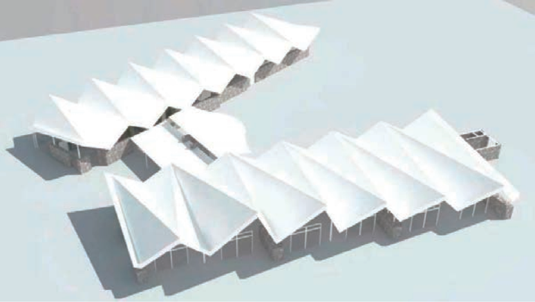
Fig 1.1
Visually the roof structure is split into two layers which sit, one on top of each other. The bottom layer is the primary load carrying structure made out of laminated timber frames, and the top layer is the cover with wooden shingles on timber purlins that extends beyond the bottom layer.
The façade is designed using structural glazing with hidden connections to the roof structure and the natural stone walls. 12m high glass fins support the façade with elegant joints (fig. 1.2).
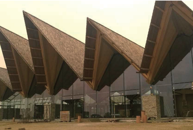
Fig. 1.2
KEYWORDS: Elegance in structure, folded roof, laminated timber, timber connections, structural glazing, glass fins, analysis.
1. INTRODUCTION
The overall architectural concept was to create a unique roof structure reflecting the surrounding terrain. The terrain to the west of the clubhouse is somewhat hilly whereas the terrain to the east is mostly flat. The roof structure reflects the terrain with tall marked rises varying from 4 to 9m towards west and less marked rises towards the cast.
Three visual materials dominate the project: Natural stone, timber and glass. The natural stone is a part of the heavy base of the building, visualising the weight and stability of the building. The timber roof structure has the appearance of a tree growing out of the stone base branching up to support the leaf-like roof, protecting the building from the weather. The glass structure is the invisible link between the natural stone walls and the roof structure that shields the building from the elements.
Visually the roof structure appears to float over the massive stone walls, with a minimum of slender support columns.
The distinct eaves of the building to the west are scaled proportionally to match the taller rises of the roof structure, which creates a coherent appearance. The eaves have a secondary function as shading which is necessary with the tall glass facade.
2. ROOF STRUCTURE
The roof structure is the most significant part of the building. The overall form was designed by the architects and then further developed and designed by the engineers using parametric design tools such as Grasshopper, hand calculations and Finite Element Analysis (FEA) programs.
There are two layers in the roof construction — the structural part and the cover. The structural part is the lower layer with laminated timber frames and fans. The cover contains insulation, eaves and ‘wooden shingles.
2.1 Shape
Both layers of the roof are folded — not like traditionally sawtooth roofs, where the folds are rectangular, but instead a folded roof shaped into triangles (fig. 1.1).
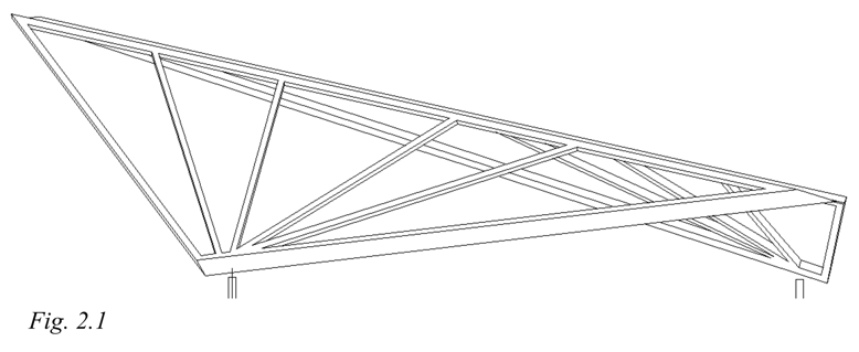
Each fold of the structural part (in the following called trusses) consists of a triangular laminated timber frame with a fan of smaller laminated timber beams inside the frame. The fan of laminated timber beams spread out from the bearing point at the column and stretch up to the upper part of the frame as shown in fig. 2.1 below. The trusses on the east wing are approximately 14 m long and 5 m high, whereas the more significant trusses on the west wing are 20-24m long and 5 — 10 m high.
2.2 Design model
The global design of the roof structure is first done by hand calculations and simplified design models. The results from the hand calculations are then verified/quantified by FEM design programs.
A local design model is made for each truss. Every truss is supported by a column in one end and the adjacent truss in the other end. This means that the trusses are dependent on each other. In the adjacent figure 2.2, it is indicated where the trusses can obtain support from its neighbour.
The fan reflects the forces natural passage through the design system to the supporting columns.
The fans within the trusses have two primary functions. The first is to stiffen the truss in its own plane. The other s to span between the upper and lower part of the frame, and cary the load perpendicular to the surface. A plywood sheet covers the whole truss, which stiffen the truss itself and works in composite with the fan beams to carry the load perpendicular to the surface.
Milled into the side of the fan beams is a notch to mount the ceiling plates. The notch distance varies, so that the fan beams appear thicker at the bottom and gradually thinner at the top — thus giving the impression of a tree growing with thinner branches at the top.
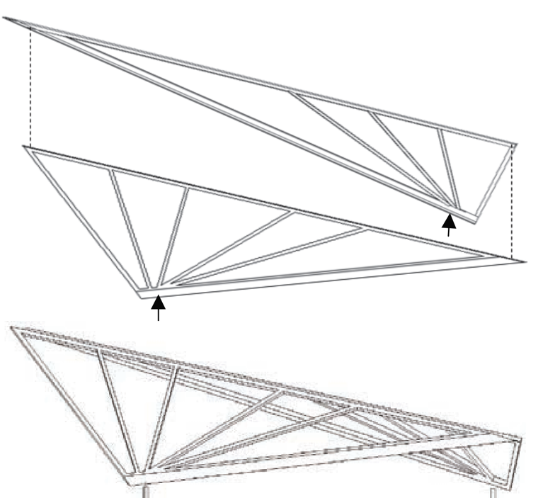
Fig. 2.2
2.3 Stabilizing system
The roof structure is carried and stabilized by cantilevered columns fastened to the natural stone
walls and cores. In the natural stone walls the columns are supported by an inclining column hidden inside the wall at all the façades except one. At the west façade of the west wing each natural stone core has columns welded to torsion and moment resisting connections in two directions. The roof structure is then stabilized in both longitudinal and transverse directions. The connections are completely hidden at the top of the natural stone cores and fastened to the underlying concrete structure by long post-tensioned steel rods inside the natural stone cores (fig. 2.3).
A slim horizontal tension rod connects the top of the columns to secure the horizontal thrust forces in the
roof structure. Besides the natural tension that occurs from the weight of the roof structure, the tension rods
are tensioned even further. Post-tensioning has. the advantage that even a slim rod can_transfer a
compression force equal to the tension in the neighbouring elements. By posttensioning the
horizontal rods, many cantilevering columns can take part in the stabilizing system.
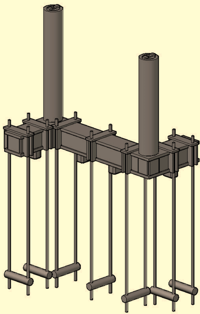
Fig. 2.3
2.4 Connections and details
The connections in the trusses between the frame and the fan beams are made with cut-outs as seen in traditional Nordic techniques (fig. 2.4). These connections also appeal to the layman and satisfy a certain intuitive feeling for the transfer of forces. The steel columns appear as if they only just touch the roof structure inside the columns perimeter, which gives the impression of an ultra-light roof structure. However, in the cavity between the trusses there is hidden a long steel plate with internal dowels connecting the steel column and the bottom frame.
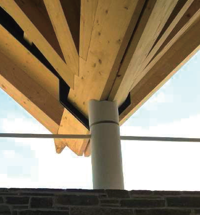
Fig 2.4
The fan beams are arranged so their centrelines intersect above the columns, thus giving an optimal load transfer with a minimum of bending moments. The angle between the fan beams is chosen in accordance with the utilization of the fan beams and possibility of load transfer points to the neighbouring truss. This has given the roof structure an aesthetically beautiful and rational geometry.
The horizontal tension rod between the columns is post-tensioned as noted in Section 2.3 The tension rod has no visible turnbuckle and meets the steel column without any traditional fork-end connections, as the turnbuckle and nuts are hidden inside the column.
The columns also function as electrical ducts to the roof for lighting, sensors, etc., as no other elements touch the roof besides the structural glazing.
The gutter on the caves is placed in the same layer as the wooden shingles, so that the gutter is invisible from undeneath and only visible as a narrow gap in the shingles (fig. 2.5).
2.5 Eaves
Each façade has caves of varied extent depending on the height of the roof structure — on the west façade of the west wing we see the most dominating caves. The caves arc held up by purlins, that cantilever out from the underlying trusses. The purlins have a smaller cross section towards the fascia, which matches the reduced stress in the purlins. The smaller cross section at the edge also hides the purlins from an oblique angel, which gives the cover of the roof a very slim expression.
The bearing elements in the roof structure along with the eaves, have a natural hierarchy which is visually satisfying. The proportions in the structure make sense and the size of the elements become a physical representation of the way the forces change throughout the structure. The same hierarchy can be found everywhere in the nature — like a tree reaching up with branches that gradually become thinner and thinner towards the top.
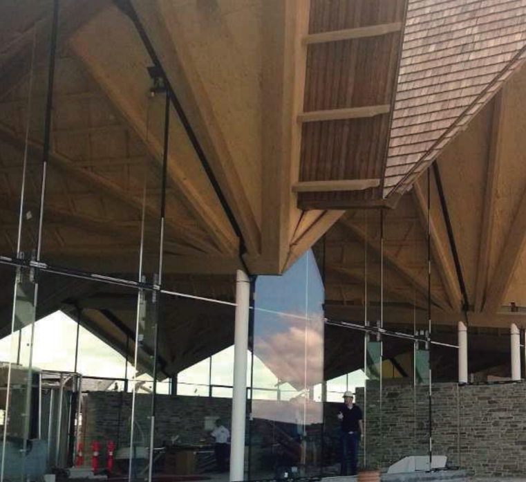
Fig 2.5
2.6 Analyses
The roof structure is simple and rational in its form and structure. As described earlier, it makes sense. But the design analysis was far from simple or trivial. Apart from the implicit stability design, ultimate limit state design and fire safety design, a numerous amount of serviceability limit state designs have been carried out.
The magnitude and direction of the deflection in the roof structure has a great impact on the glass façade and the glass walls inside the building.
The global stiffness of the roof structure is naturally large because of the form and structure of the triangular trusses; but it is not only the stiffness of the structure that has an effect on the deflections. It has proven challenging to find a useful stiffness model to base the deflection design on — a lower bound solution was therefore chosen to design the structure against excessive deformation.
The external forces such as snow, wind and dead load will not significantly affect the deformation globally due to the high stiffness in the trusses own plane; but they might affect the deformation locally for the part of the load that works perpendicular to the trusses surface. Especially the laminated timber beam which is part of the trusses frame along the caves arc highly affected by the Toads perpendicular to the surface. They carry all the loads from the purlins that holds up the caves plus the counter force.
It is not only exterior forces that may cause deflections in the roof structure. Moisture content in the wood will cause the roof structure to either shrink or swell depending on the change in moisture content. Major deflections in the roof structure will occur, as part of the roof structure is outside the building envelope (although covered). The deflection of the roof structure in relation to the moisture content change in the wood is determined for each month of the year — beginning with the month the roof is mounted. This is done for both the outside and the inside of the building.
The deflection due to moisture content change arc global and must be added to the calculated local deflections from external forces. It has been necessary to use telescopic connections at the glass façade and the inner glass walls. The telescopic connections are for the major part hidden away behind the ceiling plates.
The caves have been dynamically designed and analysed to prevent fluctuations due to wind Ioading. The analyses is based on a stiffness model using a lower bound solution.
The long steel plates that connect the roof structure and the steel columns are hidden in the cavity between the trusses. The steel connection must be centred to allow a rational load transfer to the column, which means that part of the steel plate extends outside the glass façade along with the timber construction. Using CFD to simulate the cold bridges, it has been possible to calculate the size and position of the steel plates and necessary insulation below the steel plates to avoid condensation.
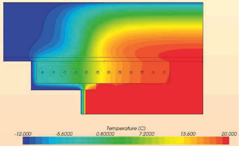
Fig 2.6
2.7 Façade
The façades are primarily made of natural stone walls and structural glazing. The west side of the west wing differs from the other facades, as this façade is much higher (up to 12m) and is almost only structural glazing with only a few natural stone cores (fig. 1.2).
Where the glass panels can’t span the distance or where windows or doors are needed, glass fins are introduced as a structural member (fig. 2.7).
The glass fins are made of toughened laminated glass and support the façade as a propped cantilever. The bottom connection is hidden by the floor build-up and the top connection works as a telescopic connection hidden behind the ceiling plates. Besides the wind load, the glass fins carry the weight of the glass panels above the openings as shear force transfer along the vertical joint.
The structural glazing solution with large panels connected to glass fins is an elegant way to build a façade with a minimum of visible structures.
3. DISCUSSION AND CONCLUSIONS
The design process was long and halted more than once as the design responsibility was unclear. Once this was established and an interdisciplinary approach was established with the architects and client, and doing all the 3D visualization along with the parametric design, the process accelerated.
The original structural analysis model for the complex roof structure was made quite simple to simulate only a few simple things. As the design process evolved, more detailed models was required, which resulted in quite a few design models and revision of previous models. It would have been more efficient to plan which result were needed in the long term before embarking on building design models to quantify only the next phase.
Choosing the glass fins to support the façade was done late in the execution phase, and as a result some of the previously intended support systems and preparations proved to be excessive.
Some of the details could have been finished to a higher degree before sending the project out to tender. Especially the details regarding the eaves and the height of the caves was determined at a late stage.
The result — though still under construction — is a beautiful and elegant structure. The triangulated folded roof with the fan of laminated beams is a unique roof structure. The hierarchy in the roof structure make sense to even the layman as it satisfy a certain intuitive feeling for the transfer of forces.
3D modelling and parametric design has been essential in solving the complex geometry as the cover and the structural part has the same overall shape but different extends, height and batter.
Having glass fins and structural glazing as a façade system is an elegant and minimalistic way to support a very high façade.
The finish of the structural members and connections is of very high quality due to the dedicated contractors and the keen eye of the client and his consultants.
4. ACKNOWLEDGEMENTS
Client: GBK
Architects: E+N
Engineers: Søren Jensen
Contractors:
Roof: Jørgen Søgaard
Steel: Bjarne Knudsen
Façade: Skandinaviska Glassystem
Concrete: Hansson & Knudsen