
International conference on structures and architecture
Af Konstruktionsingeniør Peter Vejrum og Mikkel Søndergaard
International conference on structures and architecture Juli 7-7-2022
Design and construction of a ribbed concrete slab based onisostatic lines
Vejrum, P. & Jensen, M.S.
Søren Jensen Rådgivende Ingeniørfirma A/S, Denmark
ABSTRACT: This paper tells the story of the choices and considerations made while designing an in-situ cast ribbed concrete slab based on isostatic lines. The structural typology is heavily inspired by the works of structural artist Pier Luigi Nervi. Unlike the systems made by Nervi, the boundary layout of the presented ribbed slab is asymmetrical leading to isostatic patterns with zero repeatability. State of the art digital fabrication is utilized to construct a slab where every rib pattern is unique and demands for project tolerances and surface finish are sky high.
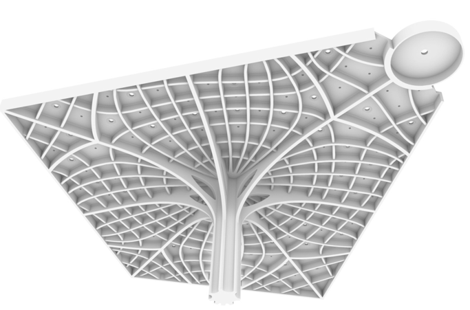
Figure 1. The ribbed concrete slab described in this paper.
1. INTRODUCTION TO THE PROJECT
As all structural engineers know, spanning planar space is inefficient. It is always important to select the right structural solution for any given project and even more so when dealing with long spanning structures as the right topology can immensely help reduce the amount of structural material required while adding elegance and coherency between the structure and the architectural project.
This paper serves as an example of how it is possible to be inspired by our engineering heritage and implement methods of designing with isostatic lines, pioneered by structural artist Pier Luigi Nervi (1891-1979) and his associates in the 1940s and 1950s, in a modern context aided by computation and digital fabrication to create elegant, ribbed topologies. In this case we used the method to create an expressive piece of structural art.
1.1. The Project
The ribbed concrete slab is part of a project that involves transformation of a 120-year-old building in the center of Copenhagen. The building is to house high grade retail facilities in the bottom two floors and office facilities in the remaining floors. The project sees the complete removal of all original inner structure and inwards facing courtyard facade while maintaining and restoring the beautiful original outwards facing brick and granite facade, copper tower and copper roof.
The building will be in-filled with new load bearing structures and floors. Given the desire to completely restore and respect the original façade, the new interior structures must respect the original floor levels. During the project we collaborated closely with architect DesignGroup Ar- chitects A/S. The construction is ongoing and the ribbed slab due to be completed in 2022.
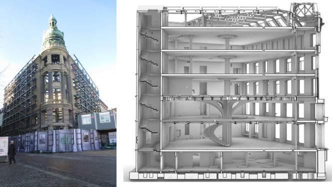
Figure 2a and 2b. Left. The lone standing façade and tower of the building after interiors had been re- moved. Right. Section through the proposed transformed building showing the mega column, ribbed slab, concrete flat slabs and suspended composite deck
1.2. Inspiration and early ideas
Having worked with the client before, in the transformation and restoration of a similar build- ing, Rømerhus in Aarhus, Denmark, we knew that ambitions for the project would be high. To- gether with the client we decided that we would aim to design new, elegant, expressive, load bearing structures in a way that would draw the public into the retail floors. To maximize the amount of available retail space we wanted to create a structural solution with a minimum of vertical elements. Given that the floor dimensions of the retail space were roughly 21 x 26 me- ters, we decided that we would need one centrally placed sculptural column in the retail space.
We wanted access to the 1st floor via a spiraling staircase around this centered column, ne- cessitating that the 1st floor had to be suspended from the 2nd floor.
Initially we considered solving the spans, upwards of 14 m, from column to façade with a composite structure of steel profiles and concrete slab. We attempted several beam layout con- figurations, but they all lacked the sculptural expressiveness we sought to add to the retail floors.
During the Italian reinforcement ban in the 1930’s and onwards Nervi, along with his associ- ates, are credited with developing several material-reducing structural solutions and systems (Halpern et. Al 2013). One of such was Ferrocement (Iori & Porett 2005), a structural material of wire mesh incased in cement that allowed Nervi to facilitate the construction of fluid struc- tural forms. Nervi used Ferrocement to cast lightweight prefabricated concrete scaffolding ele- ments from reusable molds. These elements were then used as permanent scaffolding for casting ribbed concrete slabs. To make the system feasible, the prefabricated elements needed a high level of repetition meaning that the structural layout had to be repeated and symmetrical.
We were inspired by the works of Pier Luigi Nervi, and decided we would attempt to use his method, pioneered in the “Nervi System”, to design an in-situ cast concrete ribbed slab. We would use his principal stress line method to see what isostatic patterns would emerge with our asymmetric boundary conditions.
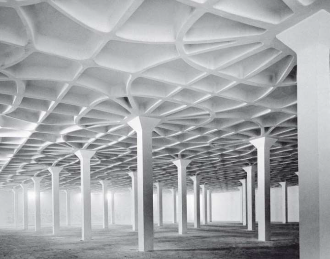
Figure 3. Gatti Wool Factory from 1953 utilizing the Nervi Floor System (Nervi 1965)
2.METHOD OF DESIGN
1.2. Principal Stress Lines Modeling
The principle of utilizing isostatics of principal bending moments, or stresses, can actually not be attributed Nervi, but instead engineer Aldo Arcangeli who worked together with Nervi in the office of Soc. Ing. Nervi & Bartoli (Halpern et. Al 2013). Aldo Arcangeli used thin plate theory to develop means of calculating isostatic lines where principal bending moment or prin- cipal stress trajectories are traced to form isostatic curves. Nervi and Arcangeli realized that if continuous elements were discretized into structural ribs oriented along the isostatic curves and the loading type and boundary conditions are kept the same, then the two structural solutions exhibit similar behavior. (Halpern et. Al 2013). Calculating the isostatic lines in the 1950’s must have been painstakingly slow but fortunately for us, modern advances in computation make the- se calculations very accessible through FEM software.
For the design of our ribbed slab, we used a parametric workflow within Rhino/Grasshopper to generate several different variations of the design we envisioned (McNeel 2021).
Principal stress lines were generated using Karamba3D FEM solver within Grasshopper (Preisinger 2021). Karamba3D calculates principal stress trajectory at point. Then traces a line a set step size to a new point, recalculates trajectory and repeats until a boundary is hit. Generat- ing the isostatic lines was easy, but deciding where to place the ribs based on the lines was not.
There can be any number of isostatic lines in a slab. Wherever the calculation of trajectories initiates, a set of isostatic curves can be generated. Some isostatic curves converge in locations making it obvious candidates for rib placement.
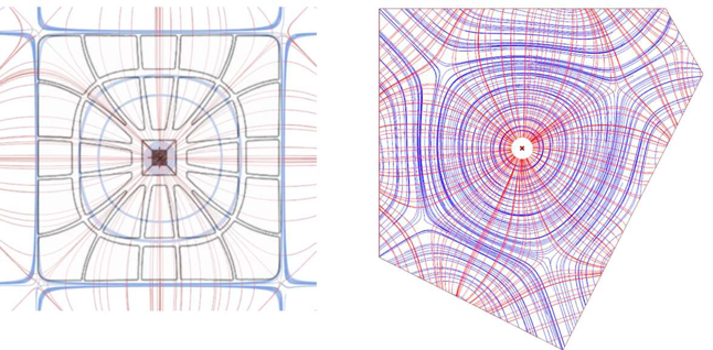
Figure 4a and 4b. We benchmarked the workflow in trying to replicate the layout of Gatti Wool Factory. When satisfactory we used the setup to generate isostatics for the retail floor layout.
Initially, like so many engineers before us, we went about trying to find the optimal set of lines to convert into ribs. Within the principal stress field there is an optimal solution for the placement of ribs within the design domain (Mueler & Tam 2015). We made several algorithms that would pick and choose isostatic lines and create FEM models to analyze, but none of them came close to the elegance and simplicity we as designers could see lying within the tumble of blue and red curves. We decided to scrap this part of our algorithm and went back to pen and tracing paper to select the calculated isostatic lines in a way that we found elegantly conveyed the natural logic of how forces flowed through the slab to its boundary supports. Luckily for us, the addition of ribs dictates the structural behavior and orients the isostatics along these ribs. We were not looking for the absolutely optimal structural solution, but the one we found most sculpturally expressive, while still adhering to the calculated principal stress trajectories.
Originally the supports along the façade were modeled as simple supports near façade pillars. This however produced a principal stress pattern we did not like. To combat this, we decided to introduce a stiff facade beam allowing the ribbed slab a continuous support along the façade. This in turn produced a much smoother pattern.
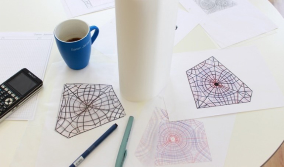
Figure 5. Tracing of ribs.
We tried many different rib configurations, and to receive instantaneous visual feedback we parametrically modeled the entire rib geometry, including column and branches based on select- ed isostatic lines as input. This level of freedom to easily explore different iterations of a design made it easier to collaborate with the project architects and settle on an isostatic configuration we both liked.
2.2. Structural Design
We decided to distinguish ribs into primary, secondary and tertiary with the heights 550, 492 and 430 mm based on layout orientation and utilization. As seen in figure 1, in the chosen lay- out we identified 8 primary rib directions that were very close to straight. These ribs flowed to- wards the corners of the slab and towards the closest façade points and would attract more load while serving as supports for the suspended composite deck below via 8 steel rods. Radially around the column, between the primary ribs, are the secondary ribs and orthogonally to both primary and secondary ribs are the tertiary ribs.
To reduce the span of the primary ribs and help with the additional weight of the suspended deck, the central column branches out to support the primary ribs near the steel rods. This reac- tion is resisted as compression through the branches and tied together through the primary ribs with additional rebars. The steel rods are not placed exactly where the branches touch the prima- ry rib, meaning that the rib needs to be designed for the increased shear and bending. To have the branches meet the steel rods the branches would need to extend too far to allow passage from the spiral staircase. To reinforce the tree aesthetic, we made the vertical section through the mega column slightly biconcave giving it a sculptural quality as well as having the primary ribs run down along the perimeter of the column.
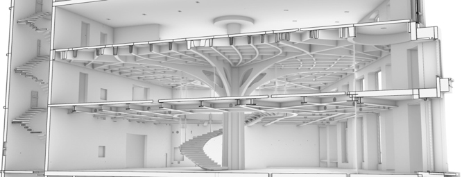
Figure 6. Branching column.
The ribs and slabs are reinforced with traditional reinforcement. Since the ribs curve in plane, we wanted reinforcement with the lowest possible diameter making it easy to bend on site. This led to slightly taller ribs as we could not stuff the section with thick rebars. Another reason for taller rib sections was a desire for high enough stiffness so that deformations would be miniscule enough allowing us to cast the structure without camber height. Camber height would make it very difficult to achieve the low tolerances we, the architect, and the client desired.
When compared to the remaining floors composed of solid 300 mm flat slabs, the added structural depth of the ribbed slab obviously has strength and stiffness benefits. Using even sim- plified calculations the ribbed slab is at least three times stiffer pr. meter slab (and probably a lot more) than the flat slabs while using roughly the same amount of material pr. m2.
The slab above the ribs is 150 mm thick. The thickness is not needed to ensure structural ca- pacity for ULS and SLS but is needed ensure sufficient fire proofing in the many integrated light- and ventilation fixtures that are cast within the slab.
The structural calculation philosophy was to simplify the complex. We used FEM models and hand calculations to determine the relative stiffness of primary, secondary, and tertiary ribs to determine the load they each would accumulate. In our engineering practice, most concrete de- sign is done using hand calculations and yield line theory to utilize the plasticity redistribution properties of reinforced concrete. This was also the case for the ribbed slab.
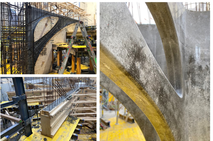
Figure 7a, 7b and 7c. Top left. Reinforcement of branch. Bottom left. Formwork and casting of branch. Right. Close-up of final finish of concrete branch.
3. FABRICATION AND MOCKUPS
Unlike the slabs created with the Nervi system, the ribbed slab in our project had no repeti- tion due to the asymmetrical nature of the building layout. In addition to this it was desired that the structure should represent itself as a one monolithic sculpture with a continuous concrete surface with an extremely high, almost polished, surface quality and very low tolerances. This excluded any means of using prefabricated elements as they would introduce noticeable joints.
In addition, the rib sections are rounded, making them difficult to produce with traditional means.
To meet the demands, the formwork is fabricated by construction robotics company ODICO A/S. They fabricate the formwork by CNC-milling large blocks of high-grade polystyrene into the negative offset of the ribbed slab. The polystyrene blocks are milled several times with dif- ferent levels of refinement. Initially an accurate, but rough shape is milled. The block is milled bellow the final size of the formwork shape. It is then coated with a type of epoxy plaster giving it a very robust and hard surface needed to avoid damaging the formwork from dropped tools or while tying rebars to the formwork. After the plaster application the shape is oversized and needs to be finely milled to end up with the final shape. Lastly, the formwork is lacquered with a ship hull paint giving it a very smooth and robust surface. Obviously, these steps are time con- suming and thus costly even though robots perform the fabrication.
The programming of the robotic mills ended up feeding back into the design of the ribbed slab as parts of the structure needed to be redesigned to make the formwork feasible to mill.
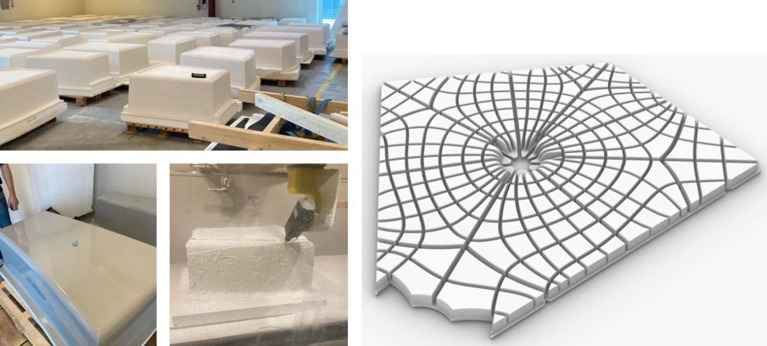
Figure 8a-8d. Left is a series of images showing the formwork pieces in various stages of fabrication. Right is a model of all the inverse formwork pieces needed to create the ribbed slab.
The separation of individual formwork pieces is thoroughly chosen and designed seeing how formwork markings are unavoidable and needs to be carefully considered when dealing with insitu-cast concrete structures.
The formwork is very lightweight, as some parts of the formwork needs to be moved manu- ally on site. The reinforcement principles, the installation and the demolding of the formwork was all essential to consider in the fabrication process, as the 400 m2 ribbed slab is to be rein- forced and cast in one go.
The formwork of the main column and the console arms are produces as compressed wooden plates which are then CNC milled and finally coated the same way as the formwork for the ribbed slab.
2.3. Mockups
More than ten 1:1 prototypes of slab sections, console branch and the main column were made during the design phase. The prototypes varied in size and complexity. The last prototype was 4x7x2 meters, and was a section of the column, one of the primary ribs and a section of the ribbed slab. The prototypes were made and tested in a period from November 2019 to April 2021. Through the process, substantial development in the resistance and smoothness of the surfaces, the connection of each piece of formwork and the possibilities of demolding, was made. The prototypes were used to test many different questions our designing team had. How could we go about casting the ribbed slab? How did coating affect the surface quality of the concrete and robustness of the formwork? How difficult would it be to remove the formwork? How should the formwork pieces be joined together to visually incorporate seams created by formwork joints?
We ended up deciding on casting the ribbed slab, branches, and column in three separate se- quences. Firstly, scaffolding and formwork for the column would be set up. The column would be cast up to the level of the suspended slab. Afterwards, formwork for the suspended hybrid slab would be set up, and the slab to be suspended in the branches would be cast. Next step would be building the formwork of the branches and remaining column section and casting the branches and remaining part of the column. Lastly, the formwork for the ribbed slab would be placed, propped and aligned to the already cast branches and column. The ribbed slab would then be cast in one go.
The prototypes revealed that removing the formwork was difficult due to very high friction between concrete surface and formwork. Removing the formwork required it to be cut apart to be removed. This meant, that no reusability of the formwork was possible, but this was not a major concern as all formwork pieces were unique. ODICO A/S worked out how to reuse the polystyrene by compressing the damaged bits into firm blocks to be repurposed.
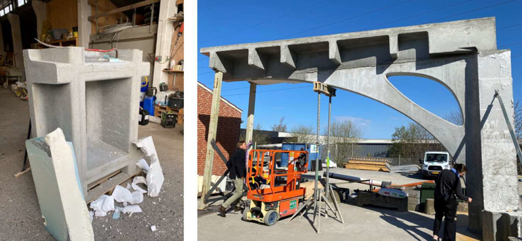
Figure 9a and 9b. Shows two of the ten mock-ups made to ensure the quality of the cast ribbed slab and to learn how to build it.
3. CONCLUSION
When first exploring isostatic curves for ribbed slab design, Nervi is quoted saying, “it was amazing to find that by thus limiting our task to the interpretation of a purely physical phenom- enon, we were able to discover unexpected and expressive new forms”. With this project the de- signing team set out to create a highly sculptural and expressive structural concept. We let our- selves be inspired by the works of Nervi to reveal, and interpret, the principal stress isostatics needed to create exactly that.
But further improvements to our design could still be done. We chose high level sculptural aesthetics and simple calculations over iterative structural optimizations using complex calcula- tion models - even though we would have liked to do that as well to shave a bit of concrete of for the sake of the rising sea levels. We believe that there might be unrealized gains to be had by reducing material usage even further.
We have spent a bit of time considering the possibilities of implementing the construction de- sign method in more projects – but for now the costs of producing the formwork is still so sub-
stantial that it will be reserved for a few handfuls of projects. However, there are possibilities for the future. The reduction of material by placing it only where necessary is going to be para- mount if we are to reduce the material usage and carbon footprint caused by the building indus- try. A 2014 study found that the isostatic ribbed slab Freiburg zoology lecture hall (a project we unfortunately first realized existed after we had designed everything), built in the 1960’s by Hecker, was comparable to state of the art post-tensioned and hollow core slabs in terms of sus- tainability and material usage (Antony et. al 2014). The study however rightly argued that the costs of the 1960’s ribbed slab would far exceed that of more approachable conventional con- struction methods.
To make the isostatic ribbed slab topology more accessible and affordable the rib sections could be designed so that the formwork could be produced with speedier hotwire cutters or sim- ple plywood boxes. The method would also be more economically feasible by reducing the de- sired surface quality making tolerances easier to work with.
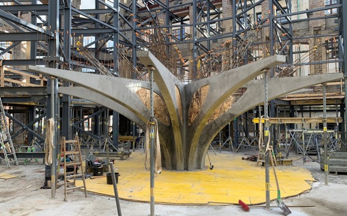
Figure 10. Current state of construction with finished branches and column.
REFERENCES
Antony, F., Grießhammer, R., Speck, T. & Speck, O. 2014. Sustainability assessment of a lightweight bi- omimetic ceiling structure. Bioinspiration & Biomimetics 9(1):016013.
Halpern, A.B, Billington, D.P. & Adriaenssens, S. 2013. The Ribbed Floor Slab Systems of Pier Luigi Nervi. Proceedings of the International Association for Shell and Spatial Structures (IASS) Symposi- um 2013 „BEYOND THE LIMITS OF MAN”.
Iori, T., Porett, S. 2005. Pier Luigi Nervi’s Works for the 1960 Rome Olympics. Actas del Cuarto Congreso Nacional de Historia de la Construcción, Cádiz, 27-29 enero 2005.
McNeel, R. & Associates. 2021. Rhinoceros. Rhinoceros. Accessed November 30, 2021. http://www.rhino3d.com/.
Mueller, C.T. & Tam, K.M. 2015. Stress Line Generation for Structurally Performative Architectural De- sign. 35th Annual Conference of the Association for Computer Aided Design in Architecture (ACADIA): Computational ecologies: design in the Anthropocene.
Preisinger, C. 2021. Karamba. Karamba. Accessed November 30, 2021. http://www.karamba3d.com/.
Nervi, P.L. 1965. Aesthetics and Technology in Building, Harvard University Press