
International conference on structures and architecture
Af Konstruktionsingeniør Rasmus Kristian Holst og Konstruktionsingeniør Andreas Castberg, IASS konferencen i Boston, August 16-20, 2018
R. HOLST, A.CASTBERG
Soren Jensen Consulting Engineers Frederiksborggade 1, 1360 Copenhagen C, Denmark
[email protected]
ABSTRACT
The Opal was to be the new landmark building for the Danish Society of Engineers (IDA) in Copenhagen. The light and hovering appearance of the addition is the result of a structural principle developed in collaboration with Dorte Mandrup Architects and Søren Jensen Consulting Engineers.
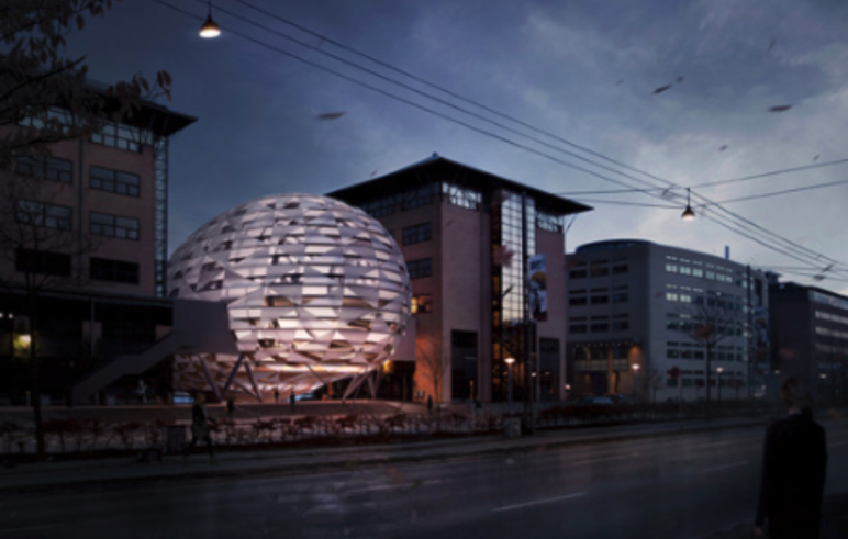
Figure 1 Vision - Dorte Mandrup Architects
KEYWORDS: Computational design, grid shell, optimization, spatial structures, interdisciplinary digital workflow
1. INTRODUCTION
The IDA Opal building containswas to contain a conference hall and restaurant with the technical room in a structure hanging below the main structure.
Placed between the existing IDA buildings near the harbour front at Kalvebodbrygge in Copenhagen, the Opal is a timber and steel hybrid diagrid shell structure in the shape of an ovoid.
The volume is carried by four V-columns placed on a single axis, moved backward from centre of the geometry allowing the building to cantilever out over the waterfront. Equilibrium is provided by tension elements in the back.
Computational design has been used as the main tool throughout the whole project to generate and systemize geometry and data necessary for the project team.
2. GEOMETRY
The geometry is created by first smoothening the original architectural ovoid shape through mesh optimisation and then cutting through the shape vertically and radially creating a simpler mesh resembling the facetted surface of an Opal.
This mesh and edges make up all the reference geometry and is sorted and shared among the project team in an online database.
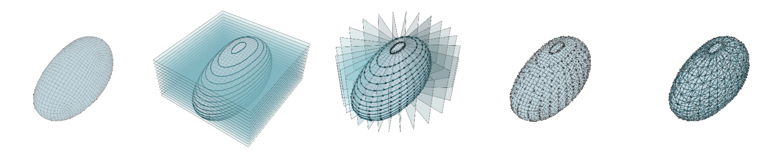
Figure 2 Basic geometry principle
3. STRUCTURE
The basic principle of cantilevering the grid shell structure is like that of a cable stayed bridge, with certain grid diagonals acting as tension cables around the doubly curved surface, four enlarged vertical grid elements at support columns leaning against each other acting as pylons and finally the floors and shell acting as the deck of a bridge
3.1. Shell
The outer steel diagrid structure acts as the skin wrapping around the vertical glulam elements representing the bones of the shell.
The steel tension and compression elements in the cantilevered shell creates the resemblance of a three- dimensional Michell Truss wrapping around the main structure.
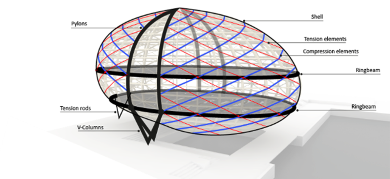
Figure 3 Principal static model
3.2 Analysis
A detailed structural FEM model, set up through a parametric Grasshopper script allows for analysis and optimisation of geometry, connections, material distribution etc.
The entire setup – including setting up load cases, materials, releases etc. - of the FEM model is done in Grasshopper so that changes are easily done and new models can be generated.
4. WORKFLOW
The freeform geometry is shaped in Rhino3D by the architects, then optimised and smoothened through Grasshopper within the engineering team.
The optimized shape acts as the base reference geometry in a series of linked interdisciplinary parametric models.
First a central parametric model sets up all gridshellgrid shell elements and central information. From the central Grasshopper model, data iswas directly exchanged to the online platform, Flux.io and thereby shared with architects, energy engineers, structural engineers and BIM managers, creating a dynamic workflow where design changes can be rapidly created and evaluated.
Evaluation data is exchanged back to the database and shared across the project team enabling members to make informed decisions.
The reference geometry from the central model is used to set up the structural FEM model. Analysis information is then sent back to the online database and hereby informs the BIM model about sizes, materials, choice of connections etc.
At the same time the sorted and named mesh is used by the architects to generate and design the façade. The architects then upload façade data to be used by the energy engineers to analyse and validate indoor climate, daylight etc.
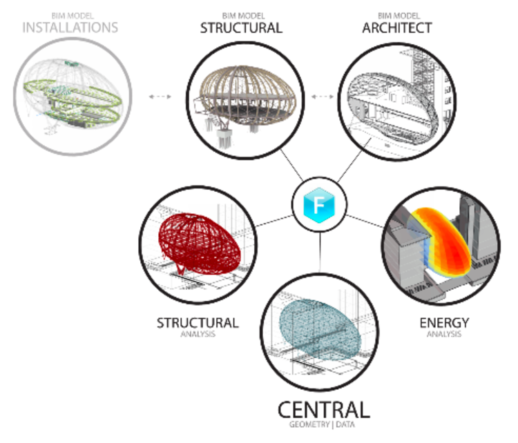
Figure 4 Digital workflow diagram
5. CONCLUSION
The digital tools have offered great opportunities in terms of evaluation, project changes and workflow that are essential when working with this kind of complex geometry where all disciplines are so closely connected and dependent on each other.
It is strongly believed that without computational design tools this project would not have been possible to carry out. At the same time the Opal projects now serves as guideline for digital design workflow processes within the Søren Jensen Engineering office.
By sitting down together as a team of architects, engineers, experts etc. to sketch and lay out basic project principles of vision, challenges and possibilities very early in the project, workflows and dynamic parametric models can be set up.
Done right, this setup can work in a way that the whole team might only really be dependent on very basic geometry updates – this could be anything from few coordinates, guide curves, simple volumes or – as for the Opal project - surface geometries.
This makes a dynamic workflow with precise and coordinated project models, where engineers doesdo not necessary have to wait for a finished architect drawing and the other way around.
The Opal is an exciting and unique structural engineering project which requires innovative methods and solutions – the combination of the digital workflow and advanced structural analysis and ideas was a great challenge and experience for the whole project team, sadly the construction of the project is on hold for reasons of economy.
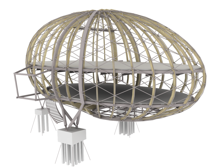
Figure 5 Construction visualization