
International conference on structures and architecture
Af Konstruktionsingeniør Duncan Horswill & Konstruktionsingeniør Andreas Castberg, IABSE Conference - Elegance in Structures, Nara Japan, Maj 13-15, 2015
Duncan HORSWILL, MEng CEng IStructE
Office Leader, Søren Jensen Consulting Engineers
Copenhagen, Denmark
[email protected]
Andreas CASTBERG, PhD Structural Engineer
Søren Jensen Consulting Engineers
Copenhagen, Denmark
[email protected]
SUMMARY: This paper describes the approach and tools used to develop the architectural and structural design concepts for a viewing tower in Aarhus, Denmark. The paper focuses on the carly stages of the design process where knowledge of the structural principles in terms of load transfer, stability, in plane stresses and deflection, were used to influence the architecture and aesthetics of the tower. The paper describes the architectural and structural concepts, the main constraints and challenges as well as an overview of the tools used to investigate various design scenarios and to communicate the effects of these to the architect.
KEYWORDS: conceptual design, creativity, digital tools, parametric modelling; structural interpreter; communication; sensitivity analysis; rapid prototyping.
1. INTRODUCTION
In 2013, an architectural competition to design a viewing tower structure located on the harbourside
in the Danish city of Aarhus was won by Dorte Mandrup Architects. The design consisted of an 11m high angular box-like form constructed from a series of flat steel plates. Each plate is perforated by holes of varying size to introduce light and transparency.
In 2014, Soren Jensen Consulting Engineers were employed to collaborate with the architect and develop the final structural scheme which would then become part of a Design and Build contract. At the time of writing, the project is about to enter the detailed design stage with completion of the project predicted in May 2015.
2. SITE AND DESIGN CONSTRAINTS
The site is a small area of land on the existing harbourside in Aarhus. The rules of the competition dictated that the footprint of the tower be constrained to an area of 10m by 10m and be located in the vicinity of some existing foundations which were originally designed for the harbour crane. The maximum load that could be imposed on the existing foundation was 20kN/m2 which corresponded to the capacity of the crane. The maximum number of people allowed to access the tower at any one time was 15 people.
Further competition rules included limiting the height of the viewing tower platform to a maximum height of 7.5m above ground level and maintaining a set distance from the nearby cycle path, lighting masts, trees and below ground services (heating pipes and electrical cables). Guidance was also provided regarding a number architectural and aesthetic requirements with respect to the overall harbourside masterplan.
3. ARCHITECTURAL AND STRUCTURAL CONCEPTS
The main purpose of the viewing tower is to provide a raised platform which can be accessed freely by the public to view the local harbourside area and adjacent waterfront. The design of the tower symbolises and emphasises the nautical and industrial history of the harbour area through its construction using exposed steel plates and its angular form which is reminiscent of the profile of a ship. Holes in the tower walls remind us of a ships portholes and add another level of visual interest. They also function as a device for allowing views out of, and light into, the tower.
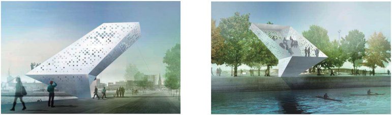
Fig. I Architects renders of the competition winning design (images by Dorte Mandrup Arkitekter)
The steel plates are inter-connected to form a stiff box-like structure which acts as a vertical cantilever to resists vertical and lateral loads and transfer them to the ground via in-plane stresses. The form of the tower is irregular and consists of a number of angular cantilevers that change direction as the tower extends up from the ground to the viewing platform at the top. The loads are transferred to the ground via a new concrete foundation consisting of concrete driven piles and an in-situ concrete pile cap and ground beam located behind the existing harbour wall.
The nature of the design is such that the architectural and structural engineering concepts are inextricably linked whereby changes to one directly affects the other.
4. STRUCTURAL DESIGN CHALLENGES
The main structural design challenges were as follows:
- Stability
- Foundation loads
- Steel plate thickness
- Deflection
- Hole distribution
It should be noted that, due to the project procurement route, Seren Jensen’s design responsibility was mainly limited to the development of the architectural and structural concepts and therefore a number of the above issues were considered but not fully addressed in terms of detailed analysis. The final design and analysis was the responsibility of the contractor.
4.1 Stability
The tower has a very small base area (2.5 x 3.0m) in relation to its overall volume which means that it is inherently unstable and very sensitive to any changes in the position of the centre of gravity relative to the centre of the base support.
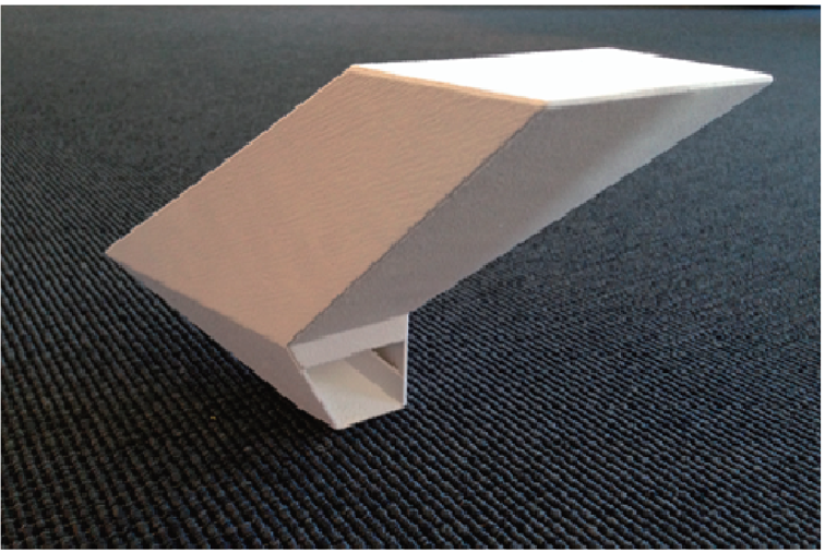
Fig. 2 3D printed scale model to show the area of the base of the tower in relation to its volume
4.2 Foundation loads
The existing foundations were designed for the load from a crane whose function it was to load and unload the docked ships. The load capacity of the existing foundation was therefore limited to a load of 20kN/m2. However it was discovered that the load from the new tower exceeded this limit and a new foundation was required.
4.3 Steel plate thickness
The steel plates were designed to transfer the vertical and lateral loads to the ground via in-plane stresses. The thickness of the plates affected the weight of the structure and the ease of fabrication and transportation. Therefore, it was important to minimise the thickness by minimising stress concentrations.
4.4 Deflection
It was important to minimise the deflection of the tower due to imposed loads in order to avoid excessive visual deformation and prevent members of the public feeling that the structure was unsafe.
4.5 Hole distribution
The architect had certain aesthetic requirements in terms of the size and distribution of holes and it was important to achieve a random appearance as opposed to a uniform pattern. Health and safety also influenced the size and location of the holes to reduce the risk of injury or falling.
5. OUR APPROACH
At the start of the project it was recognised that the tower geometry was the key to solving challenge numbers 1-4, while the in-plane stresses in the steel lems was the key to solving challenge number 5. The challenges could be reduced to the following two questions:
- What effects do changes to the architectural geometry have on the structural performance of the tower and extent of the new foundations?
- How do the in-plane stresses in the steel plates influence the size and distribution of holes in the tower walls?
Our approach was to use a combination of dynamic modelling using a parametric modelling tool (Grasshopper 3D) [1] and rapid prototyping using 3D printing. The parametric model was used to make quick changes to the tower geometry and was combined with Finite Element Analysis (FEA) as part of a structural sensitivity analysis whilst 3D printed physical models were used to test these changes and demonstrate the effects to the architect.
6. GEOMETRY MANIPULATION AND STRUCTURAL OPTIMISATION
6.1 Parametric modelling
It was decided that a parametric model of the geometry would be used so that changes to the geometry of the tower could be made quickly. Parametric modelling allows a 3D geometry model to be created from a set of geometrical parameters such as height, width, length, angle of rotation, etc. The parameters are components of computer code which use certain input data i.c. integers, which are variables. This form of 3D modelling allows geometry to be manipulated in a similar way that numbers can be manipulated using a spreadsheet.
6.2 Structural optimisation
As already stated, the form of the tower is irregular and consists of a number of angular cantilevers. The extent of the cantilevers affects the position of the centre of gravity, Therefore, by controlling the extent of the cantilevers it was possible to control the centre of gravity and its location relative to the centre of the base support.
By directly linking the parametric geometry model to an FEA program (Robot) [2] via a structural interpreter (Geometry Gym) [3] the effects of geometrical changes could be assessed in terms of stability, support reactions, material stresses and deflections. This formed the basis of a sensitivity analysis in which geometry and analysis were integrated into one seamless workflow. The efficiency of this approach allowed a large number of scenarios to be tested in a short space of time allowing the designer to develop a intuition or ‘feeling’ about what geometrical changes were beneficial and which were not. Our initial investigations focused around the stability of the tower and the loads on the foundations. These were our primary concerns as they represented the biggest risk in terms of feasibility and cost. Material stresses and deflections, though important, became secondary concerns and tended to resolve themselves as a result of satisfying the primary objectives.
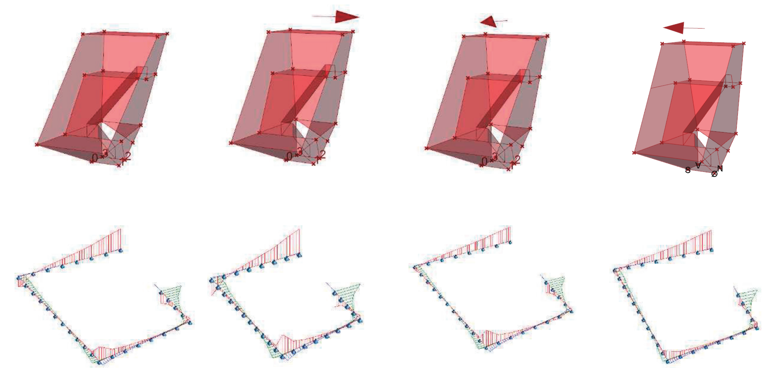
Fig. 3 Stability investigation - effect of geometry manipulation on load distribution to foundation
Ensuring that the structure was as inherently stable as possible even before any lateral loads were considered was achieved by making small geometrical changes, or ‘tweaks’, in each orthogonal direction to test how different load and ballast scenarios influenced the performance of the structure.
This led to the investigation of the loads imposed by the tower on the existing foundation and to limit these loads to the capacity of the existing foundation as well as minimising any tension forces (Fig. 3). During this process it was discovered that it was not feasible to maintain the load capacity limit and therefore a new foundation design was required.
The optimum location for the new foundation was as far away from the existing harbour wall as possible to avoid overstressing of the existing structure. Thanks to the parametric model, it was relatively easy to adapt to these new constraints and move the loads on the foundation to the desired location. This allowed the size of the foundations to be minimized which was critical both in terms of the project budget and time schedule.
Furthermore, it was discovered that the stresses in the steel plates were distributed according to the stiffness of the structure which was a function of the geometry. Therefore, it was possible to influence the distribution of stresses by manipulating the tower geometry to avoid areas of the structure from becoming stressed disproportionately to others. This was important as the weight, cost and visual expression of the structure would be affected if the plates were too thick.
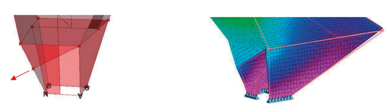
Fig. 4 Extract from geometry model (LHS) and FEA model (RHS) showing geometry and stresses at tower entrance
A number of changes were also made to the base of the tower to minimise any out of plane stresses in the steel plates. The starting concept included a triangulated plate above the tower entrance in which the comer of the plate ended in the centre of the free edge of the adjacent plate. It was evident from the FEA model that this feature resulted in significant out of plane stresses (Fig. 4) therefore the parametric model was used to ‘play’ with the geometry and find an optimum arrangement. It was also clear that the plate on the opposite side of the entrance was highly susceptible to buckling therefore the model was used to move the load path away from this sensitive area.
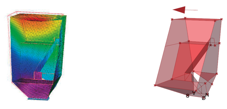
Fig 5 Extract from FEA model (LHS) and geometry model (RHS) showing deflected shape under dead load and direction of geometry manipulation to counteract deflection
In terms of deflection, this could be controlled to a certain extent through manipulation of the tower geometry. The magnitude of the deflection for example could be reduced by *pushing’ the tower in the opposite direction to its natural deflected position (Fig. 5). This allowed deflection to be controlled through geometry rather than increased material.
By adjusting the geometry in the parametric model the effect of any changes could quickly be analysed in dialog with the architect. These adjustments resulted in a more efficient architectural and structural concept that gave the architect the best possible chance of maintaining their acsthetic ambitions and the contractor the best possible chance of making an cconomic and buildable solution.
6.3 Hole distribution
Architecturally, the concept was to use a pattern of holes in the tower surfaces to give a more diffuse expression, to enhance the experience of ascending the tower and also to ensure views, especially from the upper level, and light. At the competition stage the holes were randomly sized and located according to a rotated orthogonal grid however, at the start of the main project, there was a strong desire to explore their arrangement in more detail to consider issues such as material stress.
Therefore, it was decided to extend the parametric model in order to explore the relationship between the size of the holes in the steel plates and the magnitude of the stress in the steel plates. Whereas the investigation of the effect of geometry changes described in Section 6.2 was a one-way data exchange from geometry modelling to FEM analysis, this exercise required a bi-directional ‘workflow.
The workflow started with the parametric model in which the geometry of the plates was generated. This was then linked to the FEA model via the structural interpreter software in order to analyse the stresses. The analysis results were then returned to the geometry model via the interpreter so that they could be related to the size of the holes. This relationship of material stress to hole size was inversely proportional and the model was calibrated so that no material was removed in the most highly stressed areas and the maximum allowable holes size was used where the stresses were least. Figure 6 demonstrates this workflow using a simple rectangular plate, simply supported at cach end and with two point loads at the centre of the span.
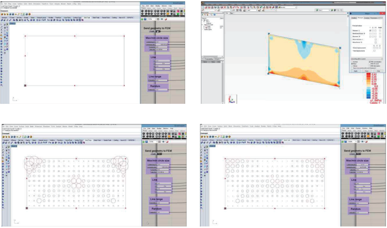
Fig. 6 Workflow used to distribute holes on a surface according to stress
Figure 7 shows the same problem but analysed using a topology optimisation process using the software Top Opt developed at DTU [4]. The dark regions indicate arcas where material has been added and the light regions where material has been removed according to the magnitude of the stress in the plate. This gives a very similar result in terms of material distribution as our approach and was used to verify the results.
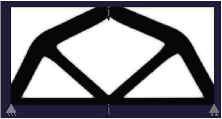
Fig. 7 Verification of hole distribution according to stress using Top Opt
The direct use of the FEA results in the distribution of the holes was not possible as the tower concept required an orthogonal grid. Therefore, the algorithm was extended to overlay the two grids and interpolate the stress at any given point.
By relating the size and distribution of the holes to the magnitude and distribution of the stresses in the plate, a discourse between structural efficiency and architectural aesthetics was set in motion that aimed to satisfy both conditions. The architectural ambition to have bigger holes at the top level of the tower was also easy to combine with the engineering logic since the stresses were smallest at the top of the tower. The final hole size and distribution was developed with the architect to include the location of the floor plates which intersected the wall plates, health and safety issues, which imposed requirements for the maximum hole diameter, and a random removal rule which automatically culled a defined number of holes to give a more random visual expression.
7. COMMUNICATION WITH ARCHITECT
Communication with the architect regarding the effects of changes to the tower geometry on the structural performance was important as it had a direct impact on the architectural expression. The parametric model was used in design team meetings to demonstrate the geometrical parameters and the effects they had on the geometry as well as the hole size and distribution.
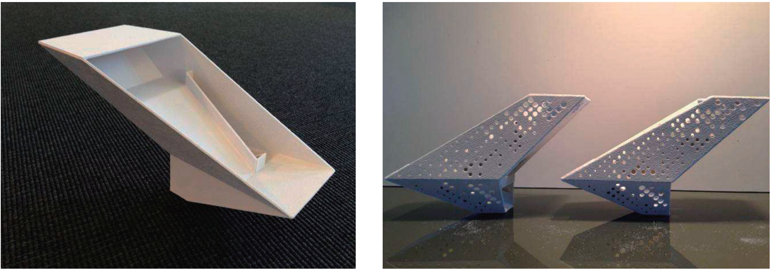
Fig. 8 3D printed scale models used to demonstrate effects of different geometrical variations
Rapid prototypes produced by a 3D printer were used to demonstrate the inherent instability of the tower and to highlight how sensitive the stability was to changes in geometry. It was found that these physical models were the best way to help all parties understand the physical properties of the tower whilst at the same time being able to qualitatively assess the effects of changes in geometry.
8. DISCUSSION, CONCLUSIONS AND ACKNOWLEDGEMENTS
The Viewing Tower project acts as a case study to demonstrate a contemporary approach to design collaboration through the use of digital design tools such as parametric modelling, structural interpreters and FEA modelling. These tools should be regarded as creative tools and as a natural extension, but not a replacement of, more traditional tools like the pencil and paper. Furthermore, they should be used as a device for technical feedback to influence the architectural concept in a way that is sensitive to the original design aspirations. This should result in a solution which is valid architecturally, structurally, practically and economically.
The use of rapid prototyping to create quick scale models of different geometrical variations also added to the dialogue between architect and engineer and helped with understanding physical properties such as stability as well as exploring the visual aspects of the tower design.
Overall, this approach allowed the main structural design challenges to be addressed in a creative ‘way so that issues such as stability, foundation loads, material stress and deflection were resolved through simple manipulation of the geometry instead of adding more steel and concrete. This resulted in a number of changes to the original concept which minimised the cost of the project whilst at the same time preserving as far as possible the original architectural vision.
A potential improvement would be to integrate a form of multi-objective optimisation algorithm (i.c. genetic algorithm) whereby the competing objectives such as stability, stress and deflection could be automatically traded off against one another instead of using a sensitivity analysis which has limitations in terms of the number of iterations that can be performed within the defined time period.
The authors would like to acknowledge Noel Wibrand and Dorte Mandrup of Dorte Mandrup Architects and thank them for their collaboration on this project and for the use of their images in Figure 1.
9. REFERENCES
[1] Grasshopper, Graphical Algorithm Editor. Developed by David Rutten. For more information see: http://www.grasshopper3d.com/
[2] Robot™, Structural Analysis Professional software, Autodesk. For more information see: http://www.autodesk.com/products/robot-structural-analysis/overview
[3] MIRTSCHIN J., Generative Models Utilized for Superior Design Development, IABSE-IASS-2011 London Symposium Report, 2011, p. 182
[4] BENDSOE M.P, Optimal Shape Design as a Material Distribution Problem, Structural Optimization 1, 193-202 (1989)